Fast roll-off filters: Are they the best choice?
Picking the right ADC/DAC filters and sample rates for your audio design
The selection of interpolation and decimation filter options in audio analog-to-digital converters (ADC) and digital-to-analog converters (DAC) is an often-misunderstood aspect of audio systems design. Selecting a fast roll-off filter to give the widest audio bandwidth isn’t always the best choice for sound quality. Filter selection is a trade-off between key performance aspects, including interaction with the analog signal path design. Listening tests suggest that selecting a filter for the best impulse response can significantly improve perceived audio quality of the system, especially at higher sampling rates.
Decimation and interpolation filters
Modern high-performance oversampling ADCs initially convert the analog input to a low-resolution, high sample rate digital signal. A digital “decimation” filter converts this low-resolution, high sample rate digital signal to the digital audio output at a typical sample rate (for example, 24-bit, 96 kHz sample rate).
Similarly, high-performance oversampling audio DACs convert a low-resolution, high sample rate signal to analog. They use a digital “interpolation filter” to convert a digital input signal, such as 24-bit, 96 kHz sample rate, to the low-resolution high sample-rate input required by the delta-sigma DAC stage.
The characteristics of these filters can make a great deal of difference in the measured and subjective audio performance of the converter. The best choice of filter may depend on the application, the external analog design, and the preferences of the designer. For this reason, many ADC and DAC ICs provide multiple selectable options for the filters.
Making the right choice
Start with the following questions to help identify the best choice for your application:
- At what sample rate(s) will the product operate? This limits the scope of the plots and specs to review. Operating at a higher sample rate comes at a high cost in resources but enables fundamentally better sound quality by relaxing the trade-offs in the interpolator/decimator filter, achieving a better impulse response for a given passband width and stopband attenuation specification.
- What flat passband does the product need? Unless your high sample-rate product objectively requires spectrally flat reproduction of ultrasonic audio, consider limiting the upper frequency of your passband spec to 20 kHz. This will enable the other performance aspects to be improved, which can make more of an improvement to the audio performance of your product.
- Does your application face EMI challenges requiring higher stopband attenuation to avoid impairment in the audible band, caused by out-of-band signal folding? Enhancements to your analog design to better filter out-of-band signal content may allow use of a filter with less stopband attenuation, which may improve audio performance, especially impulse response
- Can you choose a filter with a better impulse response? This can make a highly audible improvement to the perceived audio quality.
With these answers for your application in mind, we can explore how they affect filter choices.
Ideal filters meet the real world
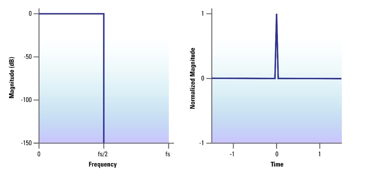
Ideally, the decimation or interpolation filter would have the frequency and time-domain characteristics illustrated in Figure 1. This shows a filter that has a flat frequency response up to the Nyquist frequency (half the sample rate and the theoretical maximum bandwidth of the sampled signal) and then complete attenuation of all higher frequencies. The time domain characteristic is perfect: an impulse input results in a one-sample impulse output, with no ringing.
 Figure 1: Frequency response and impulse response of idealized decimation/interpolation filters
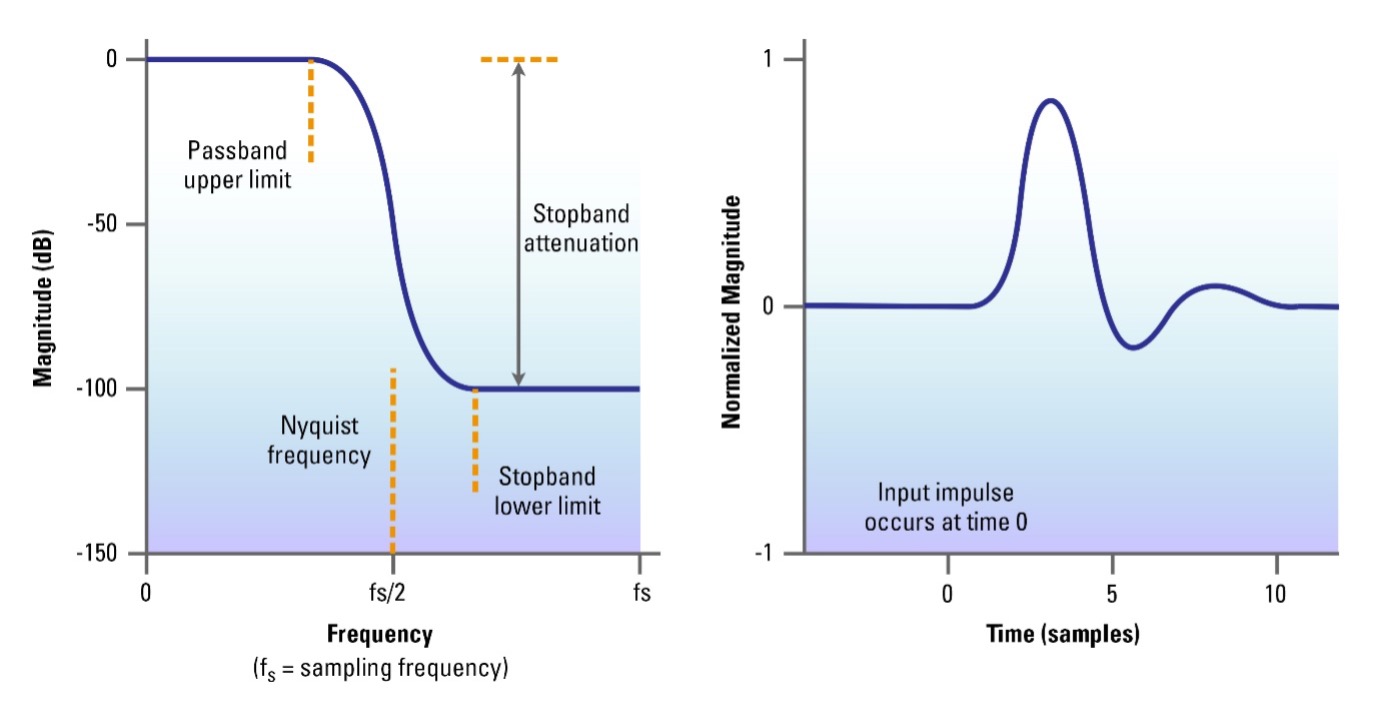
The problem is that digital filter theory makes this impossible. Real, implementable digital filters are a trade-off between different aspects of their performance, and enhancing any one of these aspects degrades one or both of the others. As illustrated in Figure 2, these aspects include:
- Flatness of the passband and the upper frequency limit of the passband relative to the Nyquist frequency
- How much the stopband is attenuated, and the lower frequency limit of the stop-band relative to the upper limit of the passband
- How much ringing there is in the impulse response
 Figure 2: Frequency response and impulse response of real decimator/interpolator filter
The wider the frequency range between the upper frequency limit of the passband and the Nyquist frequency, the less severe these trade-offs may be. It follows that for audio, where for practical purposes the upper frequency limit for the passband may be 20 kHz, higher sample rates such as 192 kHz may enable better-performing decimation and interpolation filters.
Understanding the trade-offs
What do these trade-offs mean and how do they affect the audio quality of the system? The passband flatness and extent are the easiest to understand. A flat frequency response means an authentic, high-fidelity tonal balance to the sound. Humans typically cannot hear above 20 kHz, but if your application requires high-fidelity reproduction of ultrasonic audio, then you may need to prioritize extending the passband beyond 20 kHz.
The stopband attenuation determines how well the ADC or DAC rejects spurious high-frequency content above half the sample rate. This prevents it from aliasing into the audible passband, where it degrades the distortion performance of the signal path. This may have audible effects, such as impairing clarity and stereo positioning.
For an ADC, this can be mitigated by enhancing the analog filter design on the input signal path to reduce the level of out-of-band content in the analog input signal from sources such as RF transmitters or switching power supplies. This enables selection of a decimation filter with less stopband attenuation. Conversely, if the ADC input is susceptible to high-frequency interference, then a filter with more stopband attenuation may be required.
For a DAC, it may be feasible to select an interpolation filter with less stopband attenuation if the analog output signal path has enough bandwidth to maintain linear operation in the presence of out-of-band signal energy. Conversely, if the DAC output path is more susceptible to out-of-band energy, it may be prudent to select an interpolation filter with more stopband attenuation.
The impulse response characterizes how accurately the converter handles transients, especially those with high-frequency content such as high-hats or plucked instruments. Human hearing seems surprisingly sensitive to the temporal quality of transients. It has been observed that selecting a filter with minimal impulse response ringing gives a distinct subjective impression of immediacy and realism with musical content, when compared to a filter with more impulse response ringing.
Filtering for best sound quality
It can be tempting to view filter response plots in terms of “more bandwidth sounds better” and select the filter with the greatest flat passband. But in reality, given a flat passband up to 20 kHz, the best perceived audio quality is usually obtained by selecting the filter with the best impulse response, and enhancing the analog design to improve filtering of and immunity to out-of-band content.
DACs and ADCs that feature multiple filter options, such as Cirrus Logic’s high-performance Pro Audio Family of converters, that are optimized individually for each sampling rate give the best possible impulse responses for a wide range of applications. With multiple filter options to choose from, designers can significantly improve measured and perceived audio quality of their system.
